
Posted by:
Category:
Comments:
Post Date:
Vertical Busbar Current Transformers (CTs): What They Are, Why You Need Them, and How to Choose the Right One
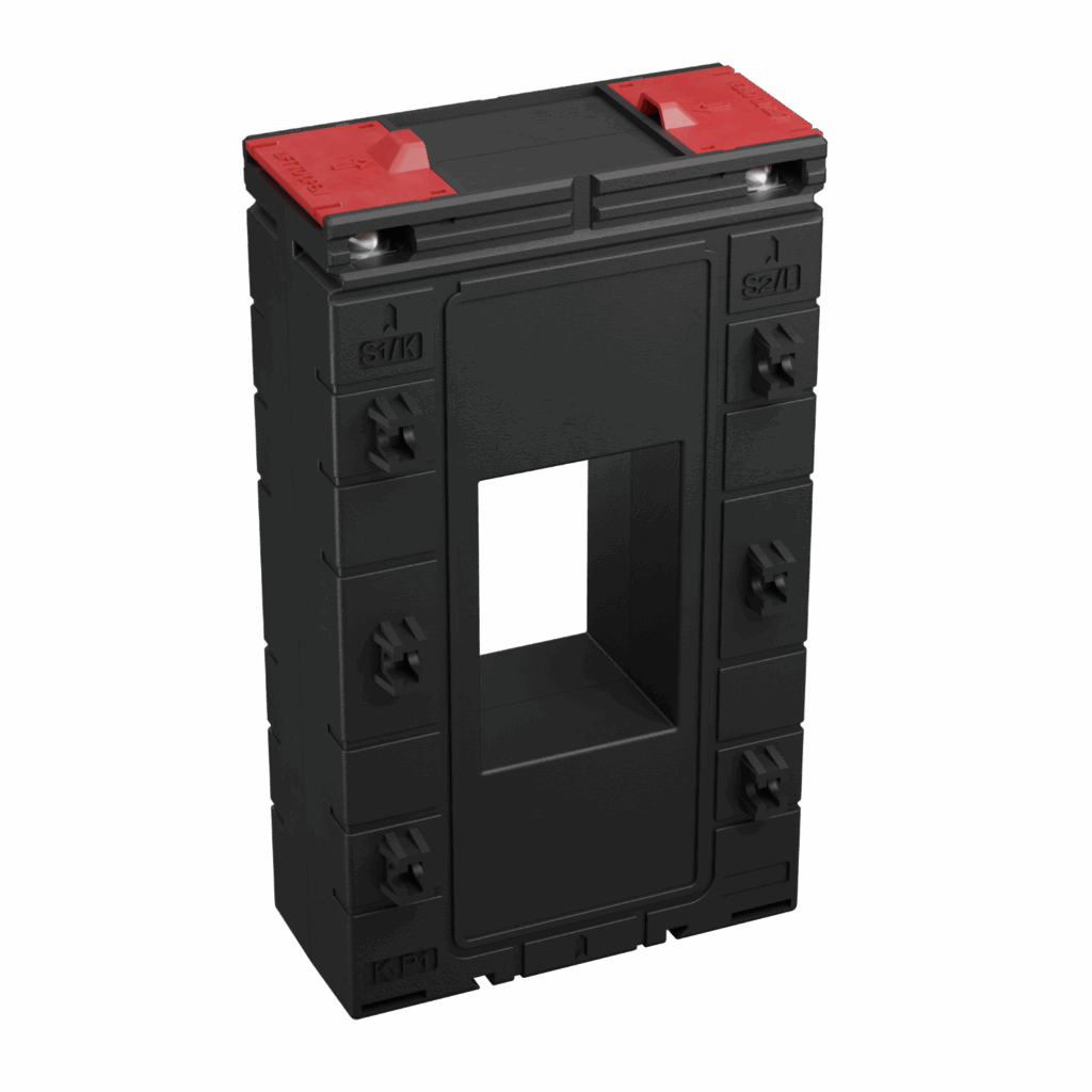
When your switchboard carries hundreds or thousands of amps on flat copper bars, the cleanest way to measure and protect those feeders is a vertical busbar current transformer (vertical CT). Unlike round, cable-through CTs, a vertical CT presents a rectangular window that matches the busbar profile, so the conductor passes straight through without cutting, crimping, or detours. The CT then steps the primary current down to a safe, standard secondary (typically 5 A or 1 A) for meters and protective relays, while providing galvanic isolation.
Why vertical CTs (and not just any window-type CT)?
Both vertical CTs and other “window-type” CTs share the idea of a through-window aperture. The difference is geometry and mounting:
- Purpose-built for busbars: The rectangular aperture sits flush on the flat face of the bar, keeping the current path straight and minimizing additional impedance or hot spots.
- Better panel ergonomics: The slim vertical form follows the busbar stack, saving depth and cable bend radius compared with circular split-core CTs around cables.
- Faster, cleaner installs: No cable cutting, lugs, or re-termination. Drop the CT onto the bar, fix, and wire the secondary.
- Repeatable positioning: Alignment along the busbar ensures consistent polarity (P1→source, P2→load) and repeatable measurement.
In short: you gain space, speed, and measurement repeatability—with fewer compromises to the busbar layout.
Why we need them: measurement, protection, and safety
- Revenue-grade & energy analytics: Vertical CTs provide accurate current signals for multifunction meters and power quality analyzers (e.g., Class 0.2S or 0.5 where specified), supporting billing, load studies, and compliance reporting.
- Protection inputs: They drive overcurrent (OC), earth-fault (EF), and other relay elements (Class 1 typical for protection/instrumentation), enabling fast, selective trip decisions that protect breakers, busbars, and downstream equipment.
- Operator safety: Technicians interact with the low-voltage secondary only; the primary path stays inside the busbar system.
- Retrofit-friendly: Ideal when you must add metering or protection to existing boards with minimal downtime.
Applications include MDBs, SMDBs, MCCs, capacitor banks, gensets/AMF panels, UPS boards, data centers, and solar/inverter switchboards.
Why vertical installation matters
Orientation isn’t just aesthetics—it’s performance and reliability:
- Thermal path & clearance: Vertical mounting preserves the natural convection channels around stacked busbars and avoids crowding adjacent devices.
- Magnetic symmetry: Centering the bar in the rectangular aperture reduces error from off-axis placement and improves repeatability between phases.
- Wiring discipline: A vertical CT keeps secondary terminals accessible along the busbar run, making shorting links and test blocks easy to standardize.
- Panel density: In high-current boards where depth is tight, vertical orientation minimizes clashes with door gear, wiring ducts, and interlocks.
Window sizes and current ratings available at GoSwitchgear
GoSwitchgear stocks vertical busbar CTs with four common window sizes to match typical LV busbar profiles:
- 40 × 60 mm
- 40 × 80 mm
- 40 × 100 mm
- 40 × 120 mm
Across these windows, we cover primary current ratings from 400 A up to 3200 A (intermediate steps included). Secondary is typically 5 A (1 A available on request for special metering runs). This spread lets you size the CT to the feeder’s nameplate and the available busbar geometry without forcing cable workarounds.
Tip: Always confirm the actual bar dimensions (including any sleeving/insulation) against the CT window. Allow clearance so the bar passes freely without stressing the case.
Accuracy classes and burdens—what to choose, when
We supply accuracy classes suited to both metering and protection:
- Class 0.2S: Precision metering and power quality analysis.
- Class 0.5: General energy metering and monitoring.
- Class 1: Protection/instrumentation (typical input for OC/EF relays).
Burden (VA) options span 2.5 VA to 30 VA, depending on primary ratio and window size. Choose a CT whose rated burden ≥ sum of connected devices + lead losses. A quick check:
- Find your meter/relay input VA from its datasheet.
- Estimate lead loss: VA≈Isec2×RleadsVA \approx I_\text{sec}^2 \times R_\text{leads} (with Isec=5 AI_\text{sec} = 5\,A or 1 A1\,A).
- Add them up and pick the next available CT burden rating above that total to preserve accuracy.
How vertical busbar CTs differ from other window types and split cores
- Rectangular vs circular aperture: A rectangle fits the busbar shape; a circle suits round conductors/cables. Using a round CT on flat bars usually wastes space or needs adaptors.
- Mechanical stability: A vertical CT clamps neatly to the bar face—no loose cable loops, no extra tie-wraps, less vibration risk.
- Lower install friction: You avoid cable disconnection, which can void warranties or add outage windows.
- Cleaner routing: Secondary wiring exits in a predictable plane, keeping segregation from control wiring simpler.
Split-core CTs still have a place (quick retrofit around cables without shutdown), but for busbar feeders, the vertical busbar CT is the most elegant, compact, and repeatable solution.
Selection checklist (save this before you spec)
- Primary ratio: Match to feeder/breaker rating (e.g., 400, 600, 800, 1000, 1200, 1600, 2000, 2500, 3200 A).
- Window size: 40×60 / 40×80 / 40×100 / 40×120 mm. Confirm insulation and tolerance clearance.
- Secondary: 5 A is standard; 1 A for long runs or when devices require it.
- Accuracy class: 0.2S (revenue/PQ), 0.5 (general metering), 1 (protection).
- Burden (VA): Ensure the CT can drive total VA at rated accuracy.
- Environment: Operating temperature, insulation class, and max system voltage.
- Compliance: Ask for test reports and ASTA certificates if your project demands them.
ASTA-certified CTs at GoSwitchgear
For projects where consultants or end users specify ASTA certification, GoSwitchgear can supply ASTA-certified vertical CTs tested by independent laboratories against the relevant BS/EN/IEC standards. ASTA certification provides confidence that critical tests—such as ratio accuracy, burden performance, insulation (dielectric) withstand, short-time current, and temperature rise—have been verified.
If your tender or specification calls out ASTA, ask our team for the current certificate set for the selected ratio/window combination. We maintain a roster of certified options and can advise on equivalent certified models when panel constraints or ratios change mid-design.
Integration examples: meters and relays
- Energy metering / MFMs / PQ analyzers: Connect three CTs (L1/L2/L3) to your meter inputs. For revenue-sensitive projects, use Class 0.2S or 0.5 and verify wiring length vs burden.
- Protection relays: CT secondaries feed overcurrent and earth-fault elements. For a sensitive earth-fault, a residual (ΣI) connection sums phase currents; choose appropriate relay settings relative to the CT ratio.
- Capacitor banks / APFC: CT input stabilizes step switching logic by measuring real feeder current instead of inferring from voltage alone.
- Genset/AMF panels: Reliable CT signals support load sharing, reverse power detection, and thermal protections.
Installation best practices
- Polarity: Maintain P1 → source, P2 → load. Consistent phase-to-phase polarity avoids vector mistakes and negative power readings.
- Secondary safety: Fit a shorting link or test block. Never open-circuit a CT secondary when primaries are energized.
- Wiring: Use twisted pair for CT leads, keep runs short, and earth one point only on the secondary (typically at the meter/relay).
- Labeling & records: Mark ratio, class, burden, and phase. Record commissioning tests (ratio, polarity, burden) for O&M.
What’s in stock at GoSwitchgear (quick view)
- Window sizes: 40×60, 40×80, 40×100, 40×120 mm.
- Primary ranges: 400 A to 3200 A (multiple steps).
- Secondary: 5 A standard (1 A on request).
- Accuracy classes: 0.2S, 0.5, 1 (availability depends on ratio/window).
- Burden options: 2.5 VA to 30 VA (model-dependent).
- ASTA-certified options: Available—share your ratio/window and we’ll match the certificate set.
For detailed matrices (ratio vs accuracy vs burden), see our datasheet or product pages. You can also download the overview here: vertical CT datasheet (PDF).
FAQ
Q: Can I reuse existing meter wiring with a new CT?
Often yes, but verify lead resistance—long runs can exceed the CT’s rated burden and erode accuracy. Consider 1 A secondary or a higher-VA CT when leads are long.
Q: Do I need 0.2S for every meter?
No. Reserve 0.2S for revenue/PQ applications. 0.5 is adequate for most plant monitoring. Use Class 1 for protection inputs.
Q: How do I size the window if my bar is sleeved?
Measure the effective bar dimensions with insulation. Choose the next larger window and ensure the CT can be fixed snugly without stressing the case.
Ready to specify?
Share your busbar size, feeder rating, meter/relay model, and any certification (ASTA) requirements. The GoSwitchgear team will recommend the optimal vertical CT—balancing accuracy, burden, availability, and panel space—so your project passes testing the first time and stays easy to maintain.
Download the vertical CT datasheet:
https://goswitchgear.ae/wp-content/uploads/2025/08/vertical-ct-data-sheet.pdf
Browse Vertical Current Transformers:
https://goswitchgear.ae/c/vertical-current-transformer/
Need a fast quote in the UAE (Dubai/Abu Dhabi)?
We stock common ratios and sizes and can arrange quick delivery across the UAE and GCC.
Share this post
Related
Posts
A Guide to Choosing AC to DC Converters for UAE & GCC Electrical Systems
Master AC to DC converters with this comprehensive guide for engineers in the UAE & GCC. Learn selection, installation, and...
A Guide to Drill Machine Prices in the UAE for Technical Professionals
Find the best drill machine price in UAE. Our 2026 guide helps contractors and engineers choose the right corded, cordless,...
A Professional’s Guide to Choosing AGM VRLA Batteries in the UAE Climate
Discover why AGM VRLA batteries are the superior power solution for UPS, solar, and industrial systems in the UAE. Get...
How to Choose the Right Lithium Ion Battery Charger for UAE & GCC Projects
Discover how to select the right lithium ion battery charger for UAE projects. This guide covers specs, BMS integration, and...