
Posted by:
Category:
Comments:
Post Date:
Electrical Insulation Resistance Testing in the UAE: A Guide to Protecting Your Assets
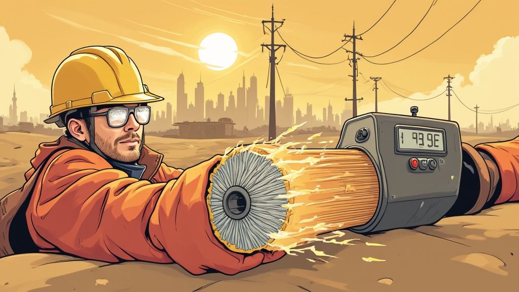
In the demanding climate of the UAE and wider GCC, ensuring the integrity of your electrical systems is non-negotiable. Think of insulation as the critical barrier keeping electricity where it belongs. Electrical insulation resistance testing is the single most important health check for wiring, motors, and switchgear, providing a clear diagnostic to prevent catastrophic failures before they happen.
Why Insulation Testing Is Critical in the UAE & GCC
In the harsh climate of the UAE and the wider GCC region, electrical systems are constantly under assault. Extreme heat accelerates material aging, high humidity introduces conductive moisture, and pervasive dust creates unseen pathways for electrical faults. These environmental stresses relentlessly break down the insulation on everything from cables to critical switchgear.
This isn't just a minor maintenance issue; it's a direct threat to your entire operation. As insulation degrades, the risk of short circuits, equipment failure, and severe hazards like electrical shock or fire increases exponentially. For any engineer, panel builder, or facility manager in Dubai, Abu Dhabi, or across the Gulf, proactively managing insulation health isn't just best practice—it's essential for operational continuity and safety.
Shifting from Reactive Fixes to Predictive Maintenance
The outdated approach of waiting for a breakdown is both costly and dangerous. Electrical insulation resistance testing allows you to shift to a modern, predictive maintenance model. By regularly testing and tracking insulation resistance values over time, you can identify signs of degradation long before a catastrophic failure occurs, safeguarding your operations and personnel.
This proactive strategy delivers tangible benefits for businesses across the GCC:
- Enhanced Safety: Identify and mitigate potential shock and fire hazards before they endanger personnel, ensuring compliance with strict regional safety regulations.
- Operational Reliability: By detecting weak points in motors, generators, and cables early, you prevent the unexpected downtime that cripples productivity and revenue.
- Extended Equipment Lifespan: Addressing insulation issues promptly helps maximize the service life of high-value assets, improving your return on investment.
- Regulatory Compliance: Regular testing provides the documentation needed to demonstrate that your installations meet the stringent requirements of international standards like IEC and local utility regulations in the UAE and KSA.
In short, insulation resistance testing is more than a routine check; it's a powerful diagnostic tool that provides a quantitative measure of an electrical system's integrity. It empowers you to make informed decisions that protect your people, equipment, and operations from the unique challenges of our region. To see the kinds of high-quality components that depend on strong insulation, check out the range of electrical components UAE professionals at GoSwitchgear rely on.
Understanding How Insulation Resistance Works
To master insulation resistance testing, you must understand the science behind the measurement. Electrical insulation is designed to resist the flow of current, but no insulation is perfect. A minuscule, generally harmless amount of current will always "leak" through. This is known as leakage current.
An insulation resistance test measures precisely how well the insulation is resisting this flow. The process is a direct application of Ohm's Law (Resistance = Voltage / Current). A specialized instrument called a megohmmeter (often referred to as a "Megger") applies a stable, known DC voltage to the conductor while simultaneously measuring the tiny current that leaks through the insulation to ground.
The tester then uses these two values—the applied voltage and the measured leakage current—to calculate the insulation resistance, displaying the result in millions of ohms, or megaohms (MΩ).
A high megaohm reading indicates healthy, effective insulation with minimal leakage. Conversely, a low reading signals a potential problem, such as moisture ingress, contamination, or material degradation—common issues for technicians in the demanding industrial environments of Dubai and Abu Dhabi.
The Three Components of Leakage Current
When you initiate a test, the total current measured by the megohmmeter is a combination of three distinct currents, each behaving differently over time. Understanding these is key to accurate diagnosis.
- Capacitive Charging Current: An initial high surge of current that fills the natural capacitance of the equipment being tested. It lasts only a few seconds and drops to nearly zero, providing no insight into insulation quality.
- Absorption Current (Polarization Current): A slower current representing the energy required to realign the molecules within the insulating material under the DC electric field. In good, dry insulation, this current starts high and gradually decreases over several minutes.
- Conduction or Leakage Current: This is the critical component—the small, steady current that flows through and over the insulation. In healthy insulation, this current should be very low and stable.
By applying the test voltage for a standardized duration (typically 60 seconds or more), we allow the capacitive and absorption currents to decay. The remaining measurement is the true leakage current, which provides the most accurate assessment of the insulation's condition.
From Current to Diagnosis
The distinct behavior of these currents enables advanced diagnostic tests. For example, if insulation is contaminated with moisture, the absorption current will not taper off as expected. Instead, a high leakage current dominates the measurement.
This principle is the basis for diagnostic tests like the Polarization Index (PI) and Dielectric Absorption Ratio (DAR), which compare resistance readings at different time intervals to assess insulation condition and detect contamination. For technicians in the UAE, this is invaluable for distinguishing between genuine insulation failure and temporary issues caused by surface condensation from high humidity. Once you grasp these core principles, you can start interpreting your test results with real confidence.
Choosing the Right Test Equipment for the Job
Accurate and safe electrical insulation resistance testing begins with selecting the appropriate tool. The ideal insulation tester, or megohmmeter, depends entirely on the application—from routine checks in a Dubai high-rise to deep diagnostics on heavy industrial machinery in Abu Dhabi.
For the daily fieldwork and troubleshooting performed by electricians and maintenance teams across the UAE, portable, battery-operated testers are the go-to solution. Their portability and ease of use are ideal for efficiently moving between assets.
However, for high-voltage applications such as large motors, generators, or transformers, more powerful equipment is required. In these scenarios, larger, line-operated benchtop units are often necessary. These models can generate higher test voltages and offer advanced diagnostic features essential for managing critical, high-value assets.
Matching Test Voltage to Equipment Rating
The single most critical factor in equipment selection is choosing the correct DC test voltage. An incorrect voltage can have severe consequences.
Applying a voltage that is too high for the equipment's insulation rating can cause permanent, irreversible damage. Conversely, using a voltage that is too low will not sufficiently stress the insulation, potentially masking underlying weaknesses that could lead to future failure.
The goal is to apply enough stress to obtain an accurate leakage current reading without causing damage. Industry standards provide clear guidelines, but a general rule is to use a DC test voltage approximately twice the equipment's AC operating voltage.
Crucial Tip: Always verify the equipment's nameplate voltage rating before beginning any test. This simple check is your primary defense against costly errors that could compromise your equipment and the validity of your results.
This table provides a reliable guide for selecting the correct DC test voltage for common AC systems found throughout the GCC, based on accepted industry best practices.
Recommended DC Test Voltages for Common AC Equipment
| Equipment Rated Voltage (AC) | Recommended DC Test Voltage |
|---|---|
| Less than 100V | 100V DC |
| 100V to 240V | 250V – 500V DC |
| 400V to 600V | 500V – 1,000V DC |
| 1,000V to 2,500V | 1,000V – 2,500V DC |
| 2,500V to 5,000V | 2,500V – 5,000V DC |
| Above 5,000V | 5,000V – 10,000V DC |
For most commercial and industrial applications in the UAE, such as testing standard 400V three-phase systems, a test voltage of 500V DC or 1,000V DC is the typical setting.
Essential Features for the GCC Climate
Equipment used in the GCC must be robust enough to withstand our unique environmental challenges. When selecting an insulation tester, certain features are non-negotiable for reliable performance in high heat, humidity, and dusty conditions.
- High IP Rating: An IP54 rating or higher is essential to protect the instrument from dust and water splashes common on worksites from Dubai to Riyadh.
- Wide Operating Temperature Range: The tester must be rated for accurate operation within the ambient temperatures experienced in the region to ensure reliable readings.
- Guard Terminal: This feature is invaluable in high-humidity environments. It bypasses surface leakage currents caused by condensation or contamination, ensuring the measurement reflects only the true insulation resistance.
Choosing the right testing equipment is the foundation of a successful predictive maintenance program. By matching the right tool and voltage to the application, you ensure every electrical insulation resistance testing procedure is both safe and effective. For professional-grade instruments and components built for our region, check out the solutions available at GoSwitchgear.
How to Perform an Insulation Resistance Test Safely
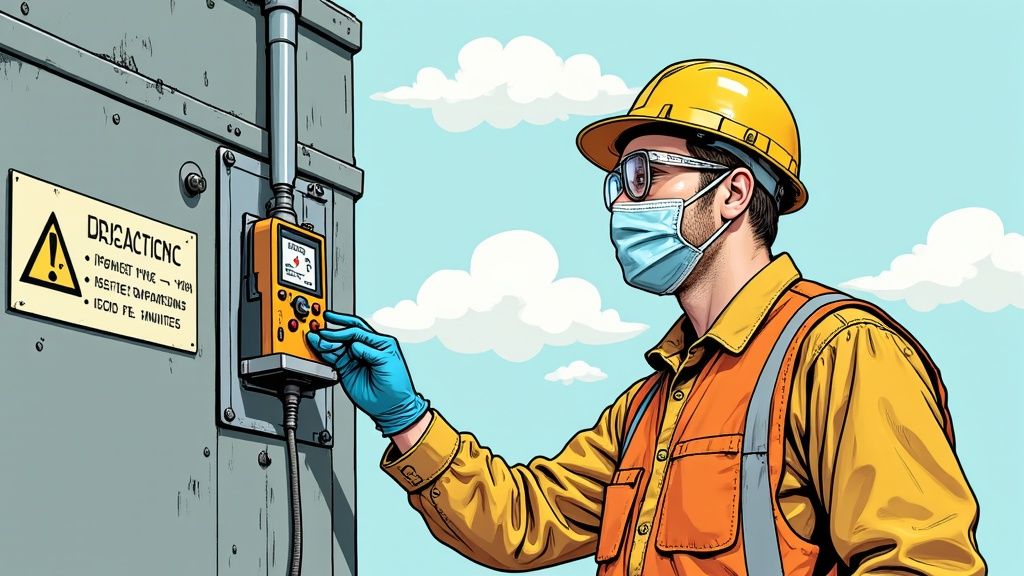
Conducting an electrical insulation resistance test is a methodical process where safety is paramount. Before connecting any leads, you must be 100% certain that the equipment is de-energized and safe to work on. This guide outlines the complete procedure for achieving safe and accurate results, tailored for conditions on worksites across the UAE.
The most critical first step is implementing strict lock-out/tag-out (LOTO) procedures. This ensures the equipment cannot be accidentally re-energized during the test. Once LOTO is in place, use a calibrated voltmeter to verify that the circuit is completely de-energized. This non-negotiable step prevents electric shock and protects both you and your test equipment.
Pre-Test Preparations for Accurate Readings
With safety confirmed, prepare the equipment. In the dusty and humid environments common in the GCC, surface contamination is a major challenge. A layer of dirt, grease, or moisture on insulators can create a conductive path for surface leakage current.
This can mislead your tester into displaying a low resistance reading, suggesting an insulation fault where none exists. To prevent false readings, thoroughly clean and dry all surfaces of bushings and insulators with a clean, dry cloth before starting.
This infographic simplifies the core testing process into three key actions.
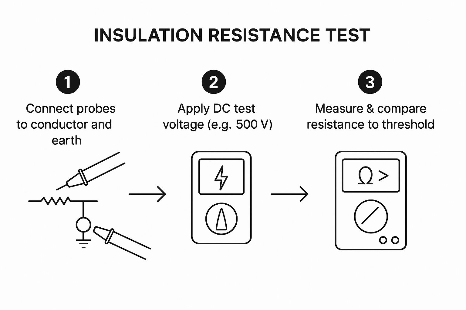
The workflow is clear: connect probes, apply voltage, and record the final measurement.
The Step-by-Step Testing Procedure
With safety and preparation complete, follow this sequence for consistent and reliable results.
Correct Lead Connection: Your megohmmeter has three leads: Line (L), Earth (E), and Guard (G).
- Connect the Line (L) lead to the conductor under test (e.g., motor winding, cable conductor).
- Connect the Earth (E) lead to the equipment's earth ground connection.
- To mitigate surface contamination, wrap a bare wire around the insulator's surface and connect the Guard (G) lead to it. This diverts any surface leakage current away from the measurement, ensuring you record only the true insulation resistance.
Select the Correct Test Voltage: As previously discussed, select the DC test voltage on your megohmmeter that corresponds to the equipment's rated AC voltage. For a standard 400V system in Dubai, you would typically select 500V DC.
Apply the Test Voltage: Press and hold the "Test" button for the standard duration of 60 seconds. This wait time is critical, as it allows the initial capacitive and absorption currents to decay, leaving a stable reading based on the true leakage current.
Record the Reading: After 60 seconds, record the insulation resistance value. Log the result with the date, time, equipment ID, and ambient temperature and humidity, as these factors can influence the measurement.
The Crucial Final Step: Safe Discharge
This is the most frequently overlooked—and most dangerous—part of the procedure. The applied test voltage stores a significant electrical charge in the equipment's capacitance, effectively turning it into a charged capacitor that can be lethal if handled improperly.
Never touch the equipment or test leads immediately after the test. The stored energy can deliver a severe electrical shock.
Modern megohmmeters are equipped with an internal circuit that automatically and safely discharges this stored energy when the test button is released. You must wait for the meter to indicate that the voltage has dropped to a safe level (typically below 25V) before disconnecting the leads.
For large equipment like high-voltage cables or motors, this discharge can take several minutes. Be patient and allow the instrument to complete its safety cycle. For added safety, use a dedicated discharge rod to short the conductor to ground, ensuring any residual charge is fully dissipated before you physically handle the equipment. Adhering to this complete procedure makes every electrical insulation resistance testing job safe, accurate, and effective.
Making Sense of Your Test Results
Obtaining a megaohm reading is only the beginning. The true skill in electrical insulation resistance testing lies in interpreting what that number means for your equipment's health. This requires diagnostic analysis, which is essential for maintaining critical infrastructure in Dubai and across the GCC.
Context is everything. The region's high ambient temperatures and humidity can significantly affect results, which is why a single, isolated reading can often be misleading.
Accounting for Environmental Factors
Temperature has a major impact. As insulating material heats up, its resistance drops. A healthy motor tested on a hot Abu Dhabi afternoon will show a lower reading than the same motor tested on a cooler morning.
To obtain a true assessment, you must either test under consistent temperature conditions or apply a temperature correction factor. Most manufacturers provide charts to normalize readings to a standard temperature (e.g., 20°C or 40°C), enabling accurate, "apples-to-apples" comparisons over time.
Beyond the One-Minute Test: The Polarisation Index
For a deeper diagnostic insight, especially in the humid coastal areas of the UAE, the Polarisation Index (PI) test is an invaluable tool. It is an advanced form of electrical insulation resistance testing that helps distinguish between healthy, dry insulation and insulation that is aged, brittle, or contaminated by moisture.
The PI test is a simple ratio of the resistance reading taken after ten minutes to the reading taken after one minute.
Polarisation Index (PI) = 10-Minute Resistance Reading / 1-Minute Resistance Reading
The principle is straightforward: In good, dry insulation, the absorption current gradually decreases over the 10-minute test, causing the resistance reading to steadily increase.
However, if the insulation is wet or contaminated, leakage current dominates. This current remains high and stable, resulting in little change in the resistance reading. A healthy system will always show a significant increase in resistance, yielding a higher PI value.
Interpreting PI Values for Actionable Insights
The PI test is a standard method for assessing insulation quality in the UAE's demanding environment and is highly effective at uncovering hidden issues like moisture, contamination, and thermal aging. For a deeper dive, you can find more about these insulation resistance test methods and their application.
This ratio provides a clear, actionable diagnostic without requiring complex analysis. The following table, based on IEEE Standard 43-2000, provides guidance for interpreting the results.
Interpreting Polarisation Index (PI) Values
| Polarisation Index (PI) Value | Insulation Condition Assessment |
|---|---|
| Less than 1.0 | Dangerous – Immediate investigation required. |
| 1.0 to 2.0 | Questionable – Requires further investigation and monitoring. |
| 2.0 to 4.0 | Good – The insulation is in acceptable condition. |
| Above 4.0 | Excellent – The insulation is in optimal condition. |
A quick assessment of the PI value can immediately tell you whether a piece of equipment requires urgent attention or is safe to operate. By integrating the PI test into your regular maintenance schedule, you equip your team with a powerful tool for predicting failures long before they can cause an outage.
Overcoming Common Testing Challenges in the GCC
Performing an electrical insulation resistance testing procedure in the GCC presents unique environmental challenges. The combination of intense heat, high humidity, and pervasive dust can significantly skew results if not properly managed.
For technicians and engineers in Dubai, Abu Dhabi, or anywhere across the UAE and KSA, understanding how to mitigate these variables is non-negotiable. Failure to do so can lead to misdiagnosing healthy equipment as faulty, resulting in unnecessary downtime and replacement costs.
Humidity is a primary concern. Airborne moisture can form a thin, conductive film on insulator surfaces, creating an alternate path for the test current and causing falsely low resistance readings that do not reflect the true condition of the insulation.
Best Practices for Reliable GCC Testing
To achieve accurate readings in the face of these regional challenges, a strategic approach is necessary.
- Timing is Everything: Schedule tests for the coolest part of the day, typically early in the morning, when lower ambient temperatures provide more stable and consistent readings.
- Cleanliness is Crucial: Before connecting test leads, thoroughly clean all insulator surfaces with a dry, lint-free cloth to remove any dust or moisture.
- Use the Guard Terminal: This feature on your megohmmeter is specifically designed to bypass surface leakage currents caused by humidity or contamination, ensuring your measurement reflects only the true insulation resistance.
Incorporating these simple yet effective steps into your routine will dramatically improve the reliability of your electrical insulation resistance testing program.
The Power of Trend Analysis
While managing environmental factors provides an accurate snapshot, true insight comes from analyzing trends over time. A single resistance reading, even when temperature-corrected, only indicates the equipment's condition at that moment. The real power lies in trend analysis.
By performing tests at regular intervals and plotting the results, you create a historical record of your insulation's health. A consistent downward trend in resistance is the most reliable early warning of degradation, even if the values remain above the minimum acceptable limit.
This proactive approach facilitates the transition from reactive repairs to predictive maintenance. Instead of waiting for a failure, you can identify a degrading asset and schedule its maintenance or replacement during planned downtime. For professionals seeking an energy management solution Dubai contractors trust, this foresight is invaluable.
The impact of humidity cannot be overstated. Data from Schneider Electric shows that insulation resistance can drop from over 500 MΩ at 40% humidity to just 4 MΩ at 95% humidity. The IEC 60947 standard advises testing below 50% humidity, highlighting why managing this variable is vital for accurate assessments in the UAE.
Insulation Testing: Your Questions Answered
Here are answers to some of the most common questions from engineers and technicians performing insulation tests on projects across the UAE.
What's the Minimum Acceptable Insulation Resistance Value?
The traditional rule of thumb is 1 Megaohm (MΩ) for equipment rated up to 1000 volts. This should be considered an absolute minimum for safety; it indicates the system is not in immediate danger of a short circuit but does not confirm its overall health.
In the demanding climate of the UAE, relying on a single value is insufficient. What truly matters is the trend. A steady decline in resistance over time, even if the reading is still above 1 MΩ, is a significant warning sign of insulation degradation. Always refer to manufacturer specifications and relevant standards like IEC 60947 for authoritative guidance.
How Often Should We Run Insulation Tests in the GCC?
The testing frequency depends on the criticality of the equipment and its operating environment.
- Critical Systems: For essential machinery exposed to the GCC heat, annual testing is recommended to prevent unexpected downtime.
- Non-Critical Systems: For equipment in climate-controlled environments, testing every 2-3 years may be sufficient.
The best practice is to develop a preventive maintenance schedule based on industry standards (such as NETA guidelines) and manufacturer recommendations. Testing is also mandatory after any major repair, modification, or when a fault is suspected.
Can an Insulation Resistance Test Actually Damage Equipment?
Yes, if performed incorrectly. The greatest risk is applying a test voltage that exceeds the insulation's design rating, which can over-stress it and cause permanent damage.
Adherence to standard procedures is non-negotiable. For a 400V AC system, a 500V DC test is standard. Always check the equipment's nameplate to confirm its voltage rating before selecting the test voltage on your megohmmeter. This simple verification takes seconds and prevents costly mistakes.
Remember, periodic electrical insulation resistance testing is about preventing failures, not causing them. As industry guides like this one on professional insulation testing emphasize, analyzing trends is far more valuable than relying on single readings. This approach has helped countless maintenance teams across the UAE significantly reduce unexpected electrical faults.
Share this post
Related
Posts
A Guide to Choosing AC to DC Converters for UAE & GCC Electrical Systems
Master AC to DC converters with this comprehensive guide for engineers in the UAE & GCC. Learn selection, installation, and...
A Guide to Drill Machine Prices in the UAE for Technical Professionals
Find the best drill machine price in UAE. Our 2026 guide helps contractors and engineers choose the right corded, cordless,...
A Professional’s Guide to Choosing AGM VRLA Batteries in the UAE Climate
Discover why AGM VRLA batteries are the superior power solution for UPS, solar, and industrial systems in the UAE. Get...
How to Choose the Right Lithium Ion Battery Charger for UAE & GCC Projects
Discover how to select the right lithium ion battery charger for UAE projects. This guide covers specs, BMS integration, and...