

A Guide to Power Factor Correction for UAE & GCC Facilities
For engineers, panel builders, and facility managers across the UAE and GCC, power factor correction is a critical strategy for optimizing electrical systems. It's a proven method to reduce energy waste, lower significant operational costs, and enhance system capacity—a non-negotiable for any modern industrial or commercial operation in the region.
What Is Power Factor and Why Does It Matter in the UAE?
Let's break this down with a simple, real-world analogy. It’s one of my favorites to use with clients because it just clicks.
Picture yourself ordering a nice, big glass of beer.
The actual liquid beer is what you really want. In electrical terms, this is the ‘real power’ (measured in kilowatts, kW). It’s the power that gets the job done—running motors, lighting up your facility, and keeping the machinery humming.
But then there's the foam on top. It’s part of the glass, but it doesn't quench your thirst. This is the ‘reactive power’ (measured in kilovolt-ampere reactive, kVAR). This type of power is essential for certain equipment—like motors, transformers, and HVAC systems—to create the magnetic fields they need to operate. But here's the catch: it does no useful work.
When the utility sends you a bill, you're paying for the entire glass—the beer and the foam. This combination is called ‘apparent power’ (measured in kilovolt-amperes, kVA).
Power factor is simply the ratio of real power to apparent power. A perfect power factor is 1.0 (or 100%). This is like getting a full glass of beer with absolutely no foam. Every bit of power you're paying for is being used productively.
A low power factor, on the other hand, means you’re getting a glass that's half foam. Your electrical system is forced to handle all that extra, non-working current, which is incredibly inefficient. You're paying for energy you can't even use.
To make these terms crystal clear, here's a quick cheat sheet.
Breaking Down Power Factor Concepts
This table is a handy reference for engineers and procurement teams to quickly understand the key terms we use when talking about power factor.
| Term | Symbol | What It Measures | The Beer Mug Analogy |
|---|---|---|---|
| Real Power | kW | The "working" power that runs your equipment. | The liquid beer—the part you actually want. |
| Reactive Power | kVAR | Power required by inductive loads (motors, transformers) that does no useful work. | The foam—it takes up space but doesn't do the job. |
| Apparent Power | kVA | The total power your system has to handle, which is what the utility bills you for. | The entire glass—beer plus foam. |
| Power Factor | PF | The ratio of Real Power to Apparent Power (kW / kVA). | The measure of how much beer you get compared to foam. A full beer mug (PF of 1.0) is the goal! |
Having these concepts down helps put the real-world consequences of poor power factor into perspective.
The Problem with Poor Power Factor
So, what happens when your power factor is low? It's a clear signal that your electrical system is inefficient, and that inefficiency comes with very real, and often very expensive, consequences for businesses here in the UAE and across the GCC.
Here are the main issues you'll run into:
- Bigger Electricity Bills: Utility providers in the region, like DEWA and ADDC, don't like inefficiency. They often hit customers with a low power factor with penalties or higher tariffs. Since you’re billed for apparent power (kVA), more "foam" means you’re literally paying for energy that does nothing for you.
- Wasted System Capacity: That extra reactive current isn't just useless; it's a freeloader taking up space in your electrical infrastructure. Your transformers, switchgear, and cables get bogged down carrying this non-working current, leaving less capacity for the power that actually makes you money.
- Overheating and Damaged Equipment: More current flowing through your system means more heat (I²R losses). This is a simple law of physics. This extra heat can dramatically shorten the lifespan of your expensive equipment and even lead to premature failure—a massive concern given the high ambient temperatures we deal with in the UAE.
- Voltage Drops: A low power factor can also cause your system voltage to sag. These drops can wreak havoc on sensitive electronics and cause motors to perform poorly or even trip out.
Crucial Takeaway: A low power factor is a direct drain on your bottom line. It forces your business to pay for energy it doesn't use while straining your electrical infrastructure and increasing maintenance costs.
Here in the GCC, our reliance on heavy-duty cooling and industrial motor loads makes this a particularly pressing issue. Think about the massive HVAC systems, pumps, and fans running in commercial towers and industrial plants. These all create significant inductive loads, which naturally drag down the power factor if you don't do something about it. Tackling this is a core part of any effective energy management solution Dubai and the surrounding region.
The good news is that the UAE is actively pushing for better energy practices. The drive for power factor correction aligns perfectly with national goals like the Dubai Clean Energy Strategy 2050. Implementing PFC solutions can cut electricity bills by up to 15% for large consumers and help you dodge those painful penalties. If you're interested in the market dynamics, you can dive deeper into the research. Read the full research about the PFC market in the UAE.
Unlock Hidden Savings and Boost System Capacity
Knowing what power factor is tells only half the story. The real incentive for any facility manager or engineer in the UAE comes down to the tangible financial and operational gains that power factor correction puts on the table. We're moving beyond technical theory here—these benefits translate directly into better profitability and a more efficient system.
The most immediate and powerful benefit? Lower electricity bills. Utility providers across the GCC, including DEWA in Dubai, often slap penalties or higher tariffs on customers with a low power factor. This isn't just a small surcharge; it can be a hefty monthly cost.
These charges show up on your bill because your facility is drawing more current (apparent power in kVA) than it’s actually putting to work (real power in kW). By installing a PFC system, you directly cancel out that wasteful reactive power, nudging your power factor closer to the perfect 1.0. This one move can completely wipe out those penalties, delivering direct, predictable savings month after month.
Free Up Your Existing Electrical System
Improving your power factor is like adding a new lane to a highway without a single day of construction. When your system is bogged down by reactive current, your transformers, switchgear, and cables are working harder than they need to. This chokes their capacity, leaving less room for productive work.
Correct your power factor, and you lift that unproductive load off the system. Suddenly, you’ve freed up a significant chunk of capacity on the electrical infrastructure you already own.
- Defer Costly Upgrades: You can now add more machinery or loads to your current system without having to shell out for larger transformers or new switchgear.
- Support Expansion: For any growing facility in Dubai or Abu Dhabi, this unlocked capacity can fuel business expansion without the massive capital expense of a full system upgrade.
- Improve System Stability: A lighter load means more stable voltage levels across your system, which is better for every piece of equipment connected to it.
This operational edge makes PFC a high-ROI investment. It’s a cornerstone of any smart energy management solution Dubai because it optimizes the assets you already have.
Key Insight: Power factor correction doesn't just cut costs; it enhances your system's capability. It allows you to power more equipment and support future growth using the infrastructure you already have in place, maximising the return on your initial investment.
Extend Equipment Lifespan and Reduce Maintenance
Every amp of current running through a wire generates heat. That extra reactive current from a poor power factor? It creates a lot of additional heat—known as I²R losses—in your transformers, busbars, and distribution cables.
In the demanding climate of the UAE and KSA, where high ambient temperatures already push equipment to its limits, this extra heat is a serious problem. It degrades insulation faster, stresses electronic components, and can lead to the premature failure of expensive assets.
By implementing power factor correction, you cut the total current draw, which in turn lowers these heat losses. This directly contributes to a longer operational life for your critical electrical components UAE and means fewer maintenance headaches. It's a vital consideration for any procurement team focused on lowering the total cost of ownership.
If you're looking to dive deeper into selecting the right systems for your needs, our guide on how to choose the right energy management solution in the UAE is a great next step.
Choosing Your Power Factor Correction Strategy
Picking the right power factor correction strategy isn't a one-size-fits-all game, especially in the diverse industrial and commercial landscape of the UAE. Your decision really comes down to your facility's load profile, day-to-day operational needs, and, of course, your budget. The path you choose will directly impact how effective and affordable your energy management solution Dubai turns out to be.
First things first, let's talk tech. PFC systems are built around two core technologies:
- Passive Power Factor Correction (PFC): This is the old-school, tried-and-true method. Think fixed or automatically switched capacitor banks. It's a robust and cost-effective solution that works brilliantly for facilities with big, stable loads, like a factory where the same machinery hums along all day.
- Active Power Factor Correction (APFC): This is the modern, more dynamic approach. It uses sophisticated electronics like an SMPS power supply to make real-time adjustments. APFC is the clear winner for places with fluctuating loads—think commercial towers with people coming and going, data centers, or any operation that relies heavily on variable frequency drives (VFDs).
Once you've got a handle on the technology, the next big question is where to put it. There are three main ways to deploy PFC equipment in your electrical system.
Centralised Correction
With a centralised strategy, you install one large automatic power factor correction (APFC) panel at a single point—typically the main low-voltage switchboard, right after the transformer. The idea is to correct the power factor for the entire facility from this central hub.
It's often the most budget-friendly option upfront because you're only buying and installing one system. This approach is a great fit for facilities with lots of small to medium inductive loads scattered around, where correcting each one individually would be a nightmare.
But there's a catch. While centralised correction cleans up your power factor at the utility meter (goodbye, penalties!), it doesn't do anything about the reactive current still sloshing around your internal distribution network. Your own cables and transformers are still carrying that extra baggage, so you miss out on reducing internal I²R losses and freeing up capacity downstream.
Just look at the numbers—effective PFC turns penalties into real savings.
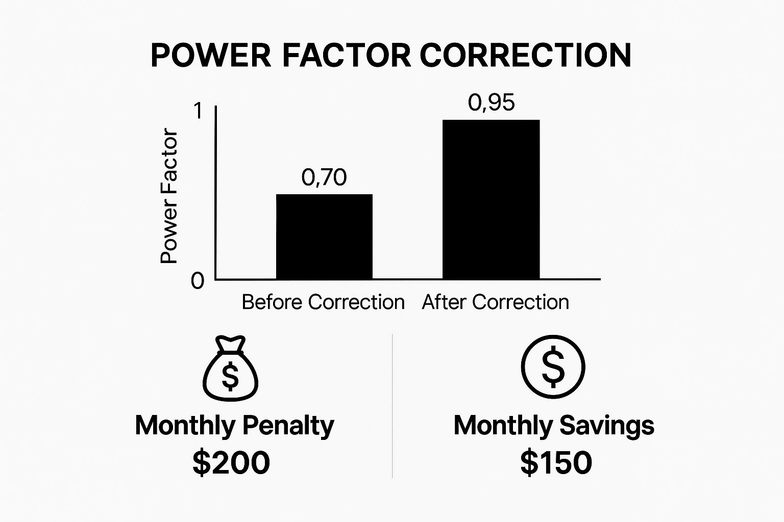
The image above shows a facility going from a poor 0.70 power factor, racking up monthly penalties, to a healthy 0.95, creating tangible savings. That's the power of getting this right.
Group Correction
Group correction strikes a nice balance. Here, you install PFC equipment at a Motor Control Center (MCC) or a distribution board that powers a specific cluster of motors or machines. This is a very common and effective strategy we see in industrial setups across the GCC.
This method gets the correction closer to the source of the problem. It doesn't just satisfy the utility company; it also cuts down the reactive current in the feeder cables running from your main switchboard to the MCC. The result? You reclaim capacity on your main distribution lines and reduce energy losses inside your own plant. It's a fantastic compromise between cost and technical benefit.
Localised Correction
Also known as individual correction, this is where you go straight to the source. A capacitor is installed directly at the terminals of a large, power-hungry inductive load, like a massive motor or transformer.
Expert Insight: From a purely technical standpoint, localised correction is the gold standard. It neutralizes reactive power right where it's created. This means your entire electrical network—from that specific machine all the way back to the grid—is free from the burden of reactive current.
This approach delivers the absolute maximum benefit for reducing system losses and freeing up capacity throughout your entire infrastructure. The downside? It's the most expensive and complicated to pull off, since it requires numerous small PFC units. We typically see it reserved for very large motors (think 50 kW and up) that run for long, continuous stretches. A prime example in a Dubai industrial zone would be a huge compressor or a primary pump motor.
How to Choose Your PFC Implementation Strategy
Making the right call demands a close look at your facility's electrical load profile and your broader business goals. To help engineers and facility managers in the UAE navigate this decision, this table breaks down the three strategies.
| Correction Strategy | Best For | Key Advantages | Potential Disadvantages | Typical UAE Application |
|---|---|---|---|---|
| Centralised | Facilities with many small, diverse inductive loads and a primary goal of avoiding utility penalties. | Lower initial cost, simpler installation and maintenance (one system). | Does not reduce I²R losses or free up capacity within the internal plant distribution network. | A large shopping mall or a commercial tower with numerous small tenants and varied, unpredictable loads. |
| Group | Industrial plants with clusters of motors or machinery fed from specific Motor Control Centers (MCCs). | A good balance of cost and performance. Reduces losses in main feeder cables and frees up some system capacity. | More complex and costly than centralised. Requires multiple PFC units. | A manufacturing plant in JAFZA correcting the power factor for an entire production line at its MCC. |
| Localised | Facilities with a few very large, continuously running inductive loads (e.g., motors >50 kW). | Maximum technical benefit. Eliminates reactive current at the source, reducing losses and freeing up capacity system-wide. | Highest upfront cost and complexity. Requires many individual units and more intricate installation. | A large water pumping station or a district cooling plant correcting a primary chiller motor. |
Ultimately, the best strategy is the one that aligns with both your technical requirements and financial constraints. By understanding these options, you can implement a power factor correction solution that not only cuts costs but also makes your entire electrical system more robust and efficient.
How to Select PFC Equipment for the GCC Climate
Choosing the right hardware for a power factor correction system goes way beyond just matching kVAR ratings. Anyone working in the UAE and wider GCC knows that our environmental conditions are demanding. Specifying components that can genuinely withstand the region’s intense heat, constant dust, and high humidity is absolutely critical for long-term reliability.
For panel builders and procurement teams, this isn't about spending more money—it's an investment in preventing premature failure and guaranteeing consistent performance. A system pieced together with subpar components might work on day one, but it will quickly turn into a maintenance nightmare, wiping out the very savings it was supposed to generate. This is exactly why sourcing high-quality electrical components UAE from proven suppliers like GoSwitchgear is so fundamental.
Specifying for High Ambient Temperatures
The extreme heat in Dubai, Abu Dhabi, and across the GCC is the number one enemy of electrical equipment. It’s a simple fact. The core components in a PFC panel, especially the capacitors and reactors, already generate their own heat during operation. When you add that to ambient temperatures that can soar past 50°C, thermal stress becomes a massive risk for failure.
To fight back, your technical specs need to put thermal resilience front and center:
- Capacitors: Don’t just grab any capacitor. Look for ones with a high maximum ambient temperature rating, specifically Class D (55°C) or even higher, per IEC 60831 standards. These are built to perform reliably without quickly degrading in our hot climate.
- Detuning Reactors: These are vital for handling harmonic distortion, but they also get very hot. You have to ensure they are designed for high-temperature operation and have plenty of thermal margin built in.
- Enclosure Ventilation: This is non-negotiable. Your APFC panel enclosures must have an effective forced ventilation system, complete with correctly sized fans and filters. The design has to promote airflow around every major component to prevent hotspots from forming.
Guarding Against Dust and Humidity
Fine dust and sticky humidity are just a part of life in our region. Dust is a real killer for electronics; it acts like an insulator, trapping heat and causing components to overheat. At the same time, moisture can lead to corrosion and dangerous short circuits. Your first line of defense is the Ingress Protection (IP) rating of your APFC panel enclosure.
Practical Guideline: For most indoor industrial spots in the UAE and KSA—think workshops, factories, and plant rooms—an IP54 rating is a solid choice. It protects against dust getting in and guards against water splashes. If you're installing outdoors or in a seriously dusty place, you'll need to step it up to something like IP65.
But it’s not just about the box. Look for internal components, like high-quality controllers, that have conformal coatings on their printed circuit boards (PCBs). This special coating shields the sensitive electronics from moisture and other contaminants, dramatically extending their life and reliability.
The Brains of the Operation: The APFC Controller
The Automatic Power Factor Controller is the heart and soul of any dynamic PFC system. It’s what makes the whole thing work. A reliable controller makes sure capacitor stages are switched in and out with precision, keeping the power factor optimized without creating damaging electrical transients.
When you're picking a controller for a GCC application, keep an eye out for these features:
- Intelligent Switching: You want a controller that uses smart algorithms. This minimizes the number of switching operations and makes sure all the capacitor stages wear out evenly over time.
- Comprehensive Monitoring: A good controller gives you real-time data on power factor, voltage, current, and harmonics. This information is gold for troubleshooting and analyzing the system's health.
- Robust Alarms: Essential protections like over/under voltage, over/under compensation, and high harmonic distortion alarms are a must. They protect the entire system from damage.
- User-Friendly Interface: A clear display and simple programming make life so much easier for the electricians and maintenance teams who have to install and look after the system.
For dependable performance in tough environments, it pays to look at options from established manufacturers. You can see what a top-tier controller offers by checking out something like the Automatic Power Factor Controller like the Nippen APFC 414-144 available through GoSwitchgear. Sourcing components that meet both IEC and local utility standards (like DEWA’s) ensures your system is not only built to last but is also 100% compliant.
Common PFC Installation Mistakes to Avoid
A perfectly designed power factor correction system can be dead on arrival because of simple, avoidable installation mistakes. For any electrician or panel builder in the UAE, getting the setup right the first time is absolutely critical to guarantee performance, safety, and the long-term ROI you’re expecting. After all, a flawless installation is what makes the system deliver on its promise to slash energy waste and cut down those utility bills.
Even one small slip-up can turn an expensive APFC panel into a useless box or, worse, create a serious hazard. Here’s a practical checklist of the most common—and critical—mistakes we see in the field. Watching out for these will ensure your energy management solution Dubai actually works as intended from day one.
Incorrect CT Placement and Polarity
This is, without a doubt, the most frequent and damaging error. Think of the current transformer (CT) as the "eyes" of the APFC controller. It measures the total load current to figure out exactly how much correction is needed. Get this wrong, and the whole system is blind.
- Wrong Location: The CT must be installed on the main incoming supply, before the APFC panel is connected. If you place it after the panel, the controller will only see the already-corrected current. It will get confused and won't switch the capacitors on, making the entire system pointless.
- Wrong Polarity: CTs have a specific direction, usually marked with P1/P2 or K/L. If you install it backward, the controller gets scrambled phase information, which leads to chaotic, ineffective switching.
Undersized Cabling and Connections
This is a dangerous oversight, especially with the high ambient temperatures we deal with in the GCC. When a capacitor bank kicks in, it draws a significant amount of current. Don't underestimate it.
Using cables that are too small is a massive fire hazard waiting to happen. The overheating alone is bad enough, but it also causes voltage drops that choke the system and reduce its effectiveness. Always, and I mean always, calculate your cable sizes based on the full rated current of each individual capacitor stage, not just the panel's overall rating. And make sure every terminal lug is crimped down tight to prevent hot spots.
Crucial Reminder: Proper cable sizing and secure terminations are not just "best practices"—they are non-negotiable safety requirements. A loose connection or an undersized wire is one of the most common points of failure that can lead to catastrophic damage.
Improper APFC Controller Settings
The APFC controller might be the brains of the operation, but it’s only as smart as the instructions you give it. The factory default settings are almost never optimized for a specific facility, whether it's in the UAE or KSA.
Here are the key settings that often get missed:
- Target Power Factor: Don't just aim for a perfect 1.0. Setting it that high can easily lead to over-correction, where your system starts pushing reactive power back to the grid. This can get you hit with a different set of utility penalties. A target of 0.98 lagging is a much safer and more common starting point.
- CT Ratio: The controller needs to be told the exact ratio of the CT you've installed (e.g., 1000/5 A). Any mismatch here, and the controller's kVAR calculations will be completely off.
- Switching Delay: This setting is your first line of defense against "hunting," which is when capacitors switch on and off too quickly. This kind of rapid cycling will absolutely destroy your capacitors and contactors, drastically shortening their lifespan.
Overlooking System Harmonics
This is a big one. Dropping a standard PFC system into a facility with high harmonic distortion is a recipe for disaster. This is especially common in modern sites packed with VFDs, LED lighting, or an SMPS power supply.
Here’s what happens: the capacitors can create a resonance condition with the existing harmonics in your system. This amplifies voltages and currents to dangerous levels, which can literally blow up the capacitors and damage other equipment nearby.
A preliminary power quality analysis isn't optional; it's essential. If your Total Harmonic Distortion (THD) is significant, you must install detuned reactors in series with the capacitors to shield the system. For any modern industrial or commercial facility, skipping this step is simply not worth the risk.
The Future of Power Quality in the MEA Region
If you think power factor correction is just a standalone fix, think again. It's actually a core piece of a much larger puzzle: the push toward smarter, more efficient energy management across the Middle East and Africa (MEA). The momentum here is undeniable. We're seeing ambitious government sustainability goals, like those in the UAE and KSA, paired with massive infrastructure projects. This combination is creating a huge demand for systems that can squeeze every last bit of value from each kilowatt.
This regional drive isn't just talk; it's backed by serious investment. The power factor correction market in the UAE and the wider MEA region is booming, thanks in large part to government programs laser-focused on energy efficiency. Projections point to strong, sustained growth fueled by huge investments in power grids, industrial plants, and brand-new urban developments. Countries like the UAE and Saudi Arabia are aggressively adopting power factor correction to cut down on electrical losses—which can waste as much as 20% of transmitted power—while also stabilizing their grids and dodging those costly reactive power penalties. You can get a closer look at the market dynamics in this full research report about the MEA PFC market.
Emerging Technologies Shaping Tomorrow's Grids
So, what does the future of power quality management actually look like? It all comes down to two things: integration and intelligence. As engineers and facility managers, we have to design electrical systems that aren't just efficient for today, but are also ready for what’s coming next. A couple of key technological shifts are really leading the way.
First, we're seeing a move toward bundling multiple solutions into a single, unified system. We’re going beyond just fixing the power factor and are now tackling total power quality.
Key Trend: The combination of Active Harmonic Filters (AHFs) with traditional APFC systems is becoming a powerful, all-in-one solution. This setup simultaneously corrects power factor and eliminates harmful harmonics, protecting sensitive electronics and ensuring complete grid compliance.
This integrated approach is absolutely essential for modern facilities filled with non-linear loads like VFDs and LED lighting.
The Rise of Smart, IoT-Enabled Controllers
The second major leap forward is the arrival of smart, IoT-enabled controllers, often integrated with advanced energy meters for the GCC market. These aren't your old-school, passive PFC panels. They are active, intelligent nodes that are part of a larger energy grid.
These advanced controllers bring a whole new set of tools to the table, going way beyond simple capacitor switching:
- Remote Monitoring: Facility managers can now keep an eye on power quality metrics from literally anywhere. This makes proactive maintenance and quick troubleshooting a reality, not a wish.
- Data Analytics: By gathering and crunching historical data, these systems can spot load patterns and fine-tune capacitor switching for peak efficiency. It’s about making smarter decisions based on real-world information.
- Grid Interactivity: Smart controllers can talk to building management systems and even the utility grid itself. The result is a more responsive, adaptive electrical network that adjusts to real-time conditions.
As facilities in places like Dubai and Abu Dhabi become increasingly automated, being able to manage power quality remotely isn't just a nice-to-have—it's a must. To really get a handle on this, check out our guide on the importance of power quality monitoring. Thinking ahead like this helps you build electrical systems that are tough, compliant, and truly ready for the future.
Your Power Factor Correction Questions, Answered
When you're dealing with electrical systems, the details matter. To help you make confident decisions, we've put together straightforward answers to the questions we hear most often about power factor correction. This is the practical stuff that engineers, panel builders, and facility managers across the UAE need to know when planning and executing their projects.
What Is an Ideal Power Factor?
In a perfect world, your power factor would be 1.0. This means 100% of the electricity you're drawing is doing real, productive work. But let's be realistic—in most industrial and commercial settings here in the GCC, hitting a perfect 1.0 all the time isn't practical or even cost-effective.
The real target, and what most utility providers like DEWA look for, is 0.95 lagging or better. If you can keep your system above this mark, you'll generally sidestep those pesky reactive power penalties on your utility bill and see some solid efficiency improvements.
Can Power Factor Be Too High?
Absolutely. It's possible to over-correct and push your power factor into a "leading" state, like 0.98 leading. This usually happens when a PFC system with fixed capacitors is connected to a load that fluctuates, causing it to pump out more reactive power than the system actually needs.
A leading power factor creates its own headaches, including:
- Voltage Instability: Over-correction can crank up voltage levels, putting sensitive electronics at risk of damage.
- Utility Penalties: You read that right. Some utilities will penalize you for a leading power factor, just like they do for a poor lagging one.
This is exactly why modern Automatic Power Factor Correction (APFC) controllers are so critical. They're smart enough to switch capacitor banks on and off as needed, holding the power factor right where it needs to be without overshooting the target.
How Is the ROI for a PFC System Calculated?
Calculating the Return on Investment (ROI) for a PFC system is surprisingly straightforward. The main factor is how much you'll save each month by getting rid of power factor penalties from your utility provider.
Simple ROI Calculation: Just take the total installed cost of the PFC system (that’s hardware plus labor) and divide it by your monthly savings from avoided penalties. That gives you the payback period in months. For instance, a system costing AED 20,000 that saves you AED 2,000 a month pays for itself in just 10 months.
When you also factor in the extra savings from lower heat losses (I²R losses) and longer equipment life, the ROI gets even better. This makes power factor correction one of the best-value energy efficiency upgrades out there and a crucial part of any modern energy management solution Dubai.
Do I Need PFC if I Don’t Pay Penalties?
Even if you aren't seeing specific power factor penalties on your bill, installing a PFC system can still bring major operational benefits. A poor power factor is a silent drag on your system, forcing higher currents through your entire internal electrical network.
By correcting it, you will:
- Cut down on heat losses (I²R losses) in your transformers, switchgear, and cables.
- Free up system capacity, which means you can add more loads without needing to pay for expensive infrastructure upgrades.
- Improve voltage stability throughout your facility, giving your motors and other sensitive equipment a longer, healthier life.
These aren't just minor tweaks; they add up to lower operating costs and a much more reliable electrical system. The value goes way beyond just dodging a penalty.
For expert advice on choosing the perfect power factor correction components for your project in Dubai, Abu Dhabi, or anywhere else in the GCC, the team at GoSwitchgear is ready to help. Reach out to our Dubai team for project support.
Explore our full range of electrical components and get project support today.


Leave a Reply