
Posted by:
Category:
Comments:
Post Date:
A Guide to Selecting the Right Cable Tray Sizes for UAE & GCC Projects
Choosing the correct cable tray sizes is fundamental to the safety, efficiency, and future scalability of any electrical installation in the demanding environments across the UAE and GCC. A well-sized system does more than just hold cables—it organizes, supports, and protects them, preventing dangerous overheating and ensuring long-term operational reliability for critical infrastructure.
Understanding Cable Tray Essentials for GCC Projects
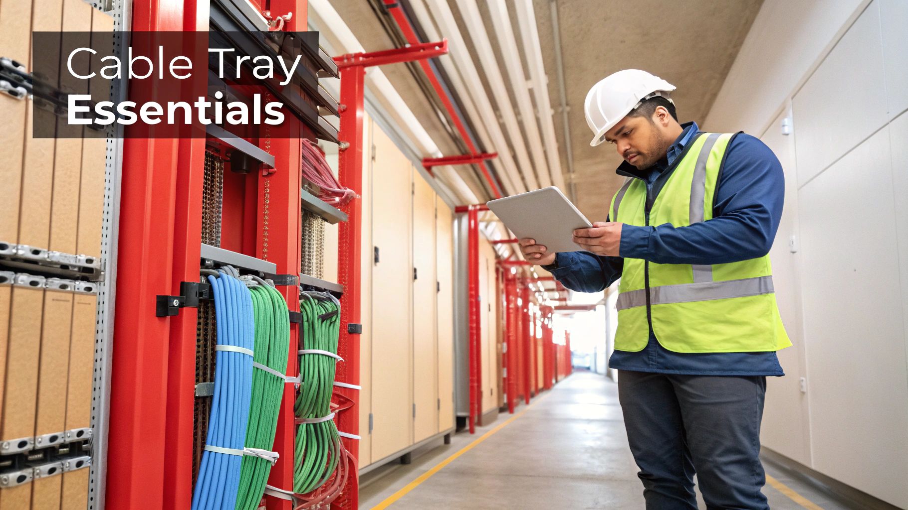
Cable trays form the structural backbone of modern electrical and data infrastructure. Their primary function is to provide a secure, organized pathway for cabling, shielding it from physical damage while allowing for critical heat dissipation—a key concern in the region's climate.
For engineers and electricians managing projects in Dubai, Abu Dhabi, and across the KSA, specifying the right dimensions is a critical decision that directly impacts project timelines, budgets, and system resilience. Undersizing a tray can lead to cable damage, performance issues, and significant fire hazards. Oversizing, on the other hand, results in wasted material, space, and capital.
Why Sizing Matters in the UAE's Climate
The unique environmental challenges in the GCC make precise cable tray selection an engineering necessity:
- High Ambient Temperatures: Adequate spacing within the tray is crucial for ventilation. Without sufficient airflow, cables can easily exceed their specified operating temperatures, leading to insulation degradation and potential failure.
- Corrosion Risk: In coastal areas like Dubai or Jeddah, high humidity and salinity demand careful material and finish selection. The wrong choice can compromise the tray's structural integrity over time.
- Future Scalability: We advise planning for 20-25% extra space within the tray during the initial design. This foresight allows for future cable additions without the need for costly and disruptive system overhauls.
This focus on robust, scalable infrastructure is driving significant market growth. For the modern utility contracting companies executing these large-scale projects, a detailed understanding of these fundamentals is non-negotiable.
A Practical Reference to Cable Tray Types
Selecting the appropriate cable tray type is as critical as determining the correct size. Across the diverse project landscape in the UAE and KSA—from industrial plants to high-tech data centers—each design offers specific advantages for cable management and protection. This choice directly influences ventilation, cable access, and structural integrity, all of which are paramount in the demanding GCC climate.
Ladder Type Cable Trays
Ladder trays are the heavy-duty solution for managing large power and control cables. Comprising two side rails connected by transverse rungs, their design provides maximum ventilation. This feature is essential for heat dissipation in the high ambient temperatures common across Dubai and the wider region.
The open structure also facilitates easy access for maintenance and future upgrades. Furthermore, ladder trays offer the greatest support span of any type, making them ideal for long, uninterrupted runs in large-scale industrial facilities.
Perforated Type Cable Trays
Perforated cable trays offer a balanced solution, combining solid support with effective ventilation. With a ventilated bottom and continuous side rails, they provide more consistent support than ladder trays, making them suitable for smaller instrumentation or data cables that could sag between rungs.
The perforations ensure adequate air circulation to prevent heat buildup. This versatility makes them a preferred choice for commercial buildings, infrastructure projects, and data centers in the UAE, where numerous smaller-diameter cables are routed together. For a detailed look at our offerings, explore our comprehensive range of cable tray and accessories.
Solid Bottom and Wire Mesh Trays
For maximum protection of sensitive cabling, solid bottom trays are the optimal choice. They provide a complete enclosure for delicate fiber optic or instrumentation cables, shielding them from dust, moisture, and falling debris. However, this total protection significantly reduces ventilation, so their use must be carefully specified based on heat load calculations.
Conversely, wire mesh trays offer unparalleled flexibility. They are lightweight, can be easily cut and shaped on-site to navigate complex routes, and their open design ensures excellent airflow. This adaptability makes them perfect for intricate pathways with numerous bends and drops, commonly found in data communications and low-voltage applications.
Standard Cable Tray Dimensions and Quick Lookup Tables
Accurate project specification begins with understanding the standard cable tray dimensions available in the market. In the UAE and across the GCC, metric units are the standard, ensuring consistency between suppliers, consultants, and contractors. This section serves as a practical reference to help your procurement and engineering teams select the right components with confidence.
The primary dimensions are width, depth (or side wall height), and length. Width determines the horizontal capacity for cables laid side-by-side, while depth dictates the vertical stacking capacity. Length, almost universally standardized at 3 metres, influences the number of supports and couplers required for a given run.
A common point of confusion is the distinction between usable depth and overall height. The usable depth is the internal space available for cables, which is the figure needed for accurate fill calculations. Always verify this dimension in the manufacturer's datasheet.
This infographic provides a quick overview of the main cable tray types, each suited for different applications and environmental conditions.
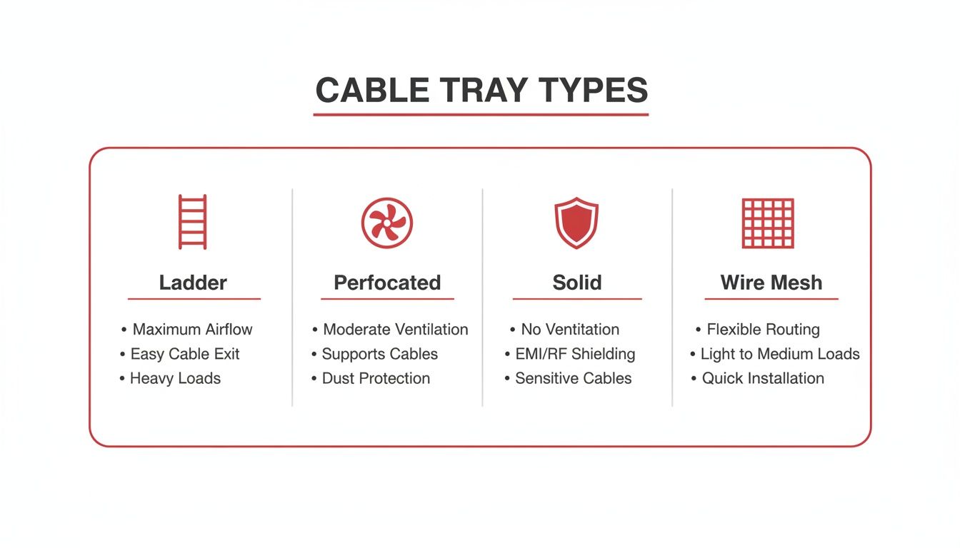
Ladder and wire mesh trays excel in ventilation, while perforated and solid bottom trays offer enhanced support and protection for the contained cables.
Quick Reference for Common Cable Tray Widths
Choosing the correct width is one of the most critical decisions in cable management design. It directly impacts cable arrangement, heat dissipation, and future expansion capacity. To simplify this process, our team at GoSwitchgear has compiled a detailed guide on standard cable tray widths and their typical applications within the GCC.
For a quick reference, the table below lists common industry-standard widths and their corresponding depths for projects from Dubai to Riyadh.
Standard Metric Cable Tray Widths and Depths
This table is a practical tool for specifying standard widths and side wall heights (depths) for ladder and perforated cable trays commonly used in the region.
| Cable Tray Width (mm) | Common Side Wall Depths (mm) | Typical Application |
|---|---|---|
| 100 mm | 50, 75, 100 | Low-voltage instrumentation, data, and communication cables. |
| 150 mm | 50, 75, 100 | Small bundles of power or control cables in commercial spaces. |
| 300 mm | 75, 100, 125, 150 | Main cable runs in commercial buildings and light industrial. |
| 450 mm | 100, 125, 150 | Sub-main power distribution in industrial facilities. |
| 600 mm | 100, 125, 150 | Heavy-duty power cables in data centres and factories. |
| 900 mm | 100, 150 | High-density cable runs for major infrastructure projects. |
Using this table ensures that specified components are readily available from local suppliers like GoSwitchgear, helping keep your project on schedule and within budget.
Calculating the Right Cable Tray Size Step by Step
Correctly calculating cable tray sizes is a critical engineering task that directly impacts system safety and project cost. An undersized tray creates an overheating hazard, while an oversized one wastes budget and space. This step-by-step guide outlines the professional process for accurate calculation.
The objective is to determine the total space occupied by all cables and select a tray that accommodates them while maintaining sufficient free space for heat dissipation—a vital consideration in the high ambient temperatures of the UAE.
Step 1: Identify All Cables and Their Diameters
Begin by creating a comprehensive inventory of every cable to be installed in a specific tray section. For each cable type, consult the manufacturer's datasheet to obtain its precise overall diameter (OD). This figure is the foundation of your calculation and must be accurate.
Step 2: Calculate the Cross-Sectional Area
Using the diameter, calculate the cross-sectional area (CSA) for each individual cable using the formula: Area = π × (Diameter / 2)².
Sum the CSAs of all cables to determine the total area your cable bundle will occupy within the tray.
For example, if you have ten cables, each with a CSA of 50 mm², the total required cable area is 10 × 50 mm² = 500 mm².
Step 3: Apply the Correct Fill Ratio
A cable tray should never be filled to 100% capacity. This is a common and dangerous mistake. Industry standards, including IEC and NEMA regulations, mandate a maximum fill ratio of 40% to 50%.
This unfilled space is critical for two reasons:
- Heat Dissipation: It allows for free air circulation around cables, preventing heat buildup and ensuring they operate within their rated temperature limits.
- Future Expansion: It provides the flexibility to add cables in the future without requiring a complete system replacement.
To calculate the minimum required internal tray area, divide your total cable CSA by your chosen fill ratio (e.g., 0.40 for 40% fill). Using the previous example: 500 mm² / 0.40 = 1250 mm². The selected cable tray must have a minimum internal cross-sectional area of 1250 mm².
Selecting Materials Built for the GCC Climate
In the GCC, material selection is as important as getting the cable tray sizes right. The region's unique combination of extreme heat, high humidity, and airborne salinity—particularly in coastal cities like Dubai and Abu Dhabi—can rapidly degrade incorrect materials, leading to corrosion, structural failure, and costly system downtime.
The choice of material directly impacts the installation's lifespan, maintenance requirements, and overall project cost. A pre-galvanised finish suitable for an indoor office environment would fail quickly in an outdoor coastal application.
Comparing Common Materials and Finishes
Each material and finish offers a different balance of corrosion resistance, strength, and cost. Understanding these trade-offs is key for engineers and procurement teams to specify the most effective solution.
- Pre-Galvanised Steel: A cost-effective choice for dry, indoor, climate-controlled environments where moisture exposure is not a concern. It offers minimal protection and is unsuitable for outdoor or harsh conditions.
- Hot-Dip Galvanised (HDG) Steel: The industry standard for most industrial and outdoor projects across the UAE and KSA. The hot-dip process creates a thick, durable zinc coating that provides excellent protection against humidity and atmospheric corrosion.
- Stainless Steel (SS316): The premium solution for the most severe conditions, such as offshore platforms, coastal industrial plants, or facilities with chemical exposure. Its superior resistance to chlorides and corrosion justifies its higher initial cost through exceptional longevity and minimal maintenance.
- Aluminium: A lightweight and inherently corrosion-resistant option ideal for applications where weight is a primary concern. Its ease of handling and installation makes it a strong choice for moderately corrosive environments.
Regional manufacturing is increasingly meeting these specific demands. This growth reduces reliance on imports and ensures projects can source compliant materials locally. This trend is evident in major projects that use modern, versatile cable trays, which can reduce installation time by up to 40% compared to traditional conduit methods. You can explore more data on this market trend to understand its impact on regional supply chains.
Comparison of Cable Tray Materials for GCC Environments
The following table provides a clear comparison to aid in selecting the right material based on the specific environmental challenges of an installation site in the GCC.
| Material/Finish | Corrosion Resistance | Relative Cost | Best Use Case in GCC |
|---|---|---|---|
| Pre-Galvanised Steel | Low | Low | Indoor, climate-controlled areas like office buildings or data centers with no direct exposure to moisture. |
| Hot-Dip Galvanised (HDG) Steel | High | Medium | The standard for most outdoor and industrial applications in cities like Dubai and Jeddah. Excellent for resisting humidity and general atmospheric corrosion. |
| Stainless Steel (SS316) | Very High | High | Essential for harsh environments with high salinity and chemical exposure, such as coastal industrial facilities, offshore rigs, and desalination plants. |
| Aluminium | Medium-High | Medium-High | Ideal for projects where weight is a primary concern and the environment is moderately corrosive. Common in applications with long spans or difficult access. |
This comparison underscores the importance of matching the material to the environment. While pre-galvanised steel is economical for protected indoor use, HDG steel provides the balanced performance needed for most outdoor projects. For the most demanding coastal or industrial sites, the superior resistance of SS316, despite its higher initial cost, ensures long-term reliability and avoids premature failure.
Getting Load Capacity and Support Spacing Right
The structural integrity of a cable management system depends on the precise relationship between load capacity, tray dimensions, and support spacing. This is an engineering calculation, not an estimation. Correctly specifying these parameters is essential to prevent system sagging and ensure long-term structural safety.
The tray's material, thickness (gauge), and side rail height directly determine its load-bearing capacity. For example, a Hot-Dip Galvanized steel tray with 100 mm side rails will support a significantly heavier cable load over the same span compared to a pre-galvanized tray with 50 mm rails.
NEMA and IEC Load Classifications
To ensure consistency, international standards bodies like NEMA (National Electrical Manufacturers Association) and IEC have established standardized load classes. These guidelines are the definitive reference across the GCC for specifying system strength.
For example, a tray with a NEMA 20C classification is certified to safely support a load of 100 lbs/ft (approx. 149 kg/m) over a 20-foot (6-meter) support span. Adherence to these classes is a non-negotiable aspect of project safety and compliance.
How to Determine Support Spacing
The maximum allowable distance between supports is determined by the tray's load class and the total weight of the cables (including a provision for future additions).
Key considerations for proper support spacing include:
- Preventing Deflection: Proper spacing prevents the tray from sagging under the cable load. Sagging can strain cable insulation and compromise the integrity of the entire system.
- Splice Plate Placement: NEMA VE 2 guidelines recommend placing splice joints at one-quarter of the span distance from a support. This positioning minimizes stress on connection points.
- Supporting Fittings: Bends, tees, risers, and other fittings require dedicated supports near each end. Refer to our guide on electrical cable tray accessories for detailed specifications.
Miscalculation of these factors is a leading cause of cable tray system failures, particularly in demanding industrial environments where systems are subjected to constant operational stress.
Navigating Local and International Standards
For projects in the UAE and the wider GCC, compliance with regulatory requirements is not merely administrative; it is essential for the safety, reliability, and legal approval of an electrical installation. Non-compliance can lead to failed inspections by authorities like DEWA, resulting in project delays, costly rework, and significant financial penalties.
All cable management systems must comply with specific local and international standards.
The primary international standard is IEC 61537, which defines the requirements for cable tray and ladder systems and is strictly enforced in the region. Additionally, guidelines from NEMA (National Electrical Manufacturers Association) are widely referenced, particularly NEMA VE 1 for manufacturing standards and NEMA VE 2 for installation best practices.
Adherence to these standards is mandatory. Attempting to use non-compliant materials can halt a project during inspection phases, especially with local authorities and utility providers in Dubai, Abu Dhabi, and across the KSA.
The most reliable way to ensure compliance is to partner with a supplier that adheres to these regulations. Sourcing components from a trusted specialist like GoSwitchgear guarantees certified products that meet the stringent safety and performance benchmarks required in the GCC, ensuring your project is safe, compliant, and built for longevity.
Cable Tray Sizing: Your Questions Answered
Our engineering team at GoSwitchgear frequently addresses key questions about specifying cable trays for projects in the UAE and GCC. Here are expert answers to the most common queries.
What is the correct cable tray fill ratio for GCC projects?
The industry standard, guided by IEC norms and local regulations, specifies a maximum fill ratio between 40% and 50%. This is a critical safety margin, not a mere recommendation. In the high ambient heat of the GCC, this empty space is essential for proper heat dissipation, preventing cables from exceeding their operational temperature limits. It also provides necessary capacity for future expansion.
When should I choose ladder vs. perforated trays?
The choice depends on two primary factors: cable type and ventilation requirements.
- Ladder Trays: Ideal for heavy-duty power cables that generate significant heat. Their open design provides maximum airflow and simplifies cable access for maintenance.
- Perforated Trays: The better choice for smaller instrumentation, control, or data cables. They offer more continuous support to prevent sagging while still providing good air circulation.
Why is Hot-Dip Galvanized Steel the default choice in the GCC?
Hot-Dip Galvanized (HDG) steel offers the optimal balance of high corrosion resistance and cost-effectiveness for the regional climate. The thick, protective zinc coating created during the galvanizing process provides robust defense against the hot, humid, and often saline air found in coastal cities like Dubai and Abu Dhabi. This ensures the long-term structural integrity and reliability of the cable management system.
Share this post
Related
Posts
A Guide to Choosing AC to DC Converters for UAE & GCC Electrical Systems
Master AC to DC converters with this comprehensive guide for engineers in the UAE & GCC. Learn selection, installation, and...
A Guide to Drill Machine Prices in the UAE for Technical Professionals
Find the best drill machine price in UAE. Our 2026 guide helps contractors and engineers choose the right corded, cordless,...
A Professional’s Guide to Choosing AGM VRLA Batteries in the UAE Climate
Discover why AGM VRLA batteries are the superior power solution for UPS, solar, and industrial systems in the UAE. Get...
How to Choose the Right Lithium Ion Battery Charger for UAE & GCC Projects
Discover how to select the right lithium ion battery charger for UAE projects. This guide covers specs, BMS integration, and...